Introduction
LinkRunner AT 1000/2000 Network Auto-Tester enables you to quickly verify Ethernet copper and fiber (2000 model only) cables, network connectivity and availability. In addition, the tester can be used for identifying the network device to which it is connected. It identifies PoE ports, provides a Report generating function, and can serve as a packet reflector for Fluke Networks performance tests. You can also transfer and view reports on LinkRunner Manager.
LinkRunner AT 1000/2000 Network Auto-Tester is hereafter referred to as the LR-AT
Registering Your Product
Registering your product with Fluke Networks gives you access to valuable information on product updates, troubleshooting procedures, and other services. To register, fill out the online form on the Fluke Networks website at www.flukenetworks.com/registration.
The Fluke Networks Knowledge Base
The Fluke Networks Knowledge Base gives answers to common questions about Fluke Networks products and includes information on technology and procedures for network and cable tests. To see the Knowledge Base, go to www.flukenetworks.com, then click Support > Knowledge Base.
Safety Information
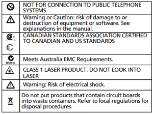
Table 1 gives descriptions of the safety symbols used on the tester and in this manual.
Warning
Use only the ac adapter provided to charge the battery
Warnings
To avoid possible electric shock or personal injury,
follow these guidelines:
- Do not use this product if it is damaged. Before using the product, inspect the case. Look for
cracked or missing plastic.
Do not operate the product around explosive gas, vapor or dust.
- No serviceable parts.
- Do not try to service.
- If this product is used in a manner not specified by the manufacturer, the protection provided by the product may be impaired.
Warning Class 1 Laser Product
With an optional SFP fiber adapter installed, this product will contain a Class 1 laser. Do not look into the laser port because this may cause eye injury.
Cautions
Use the proper terminals and cable for all connections.
Unpacking
The LinkRunner AT tester comes with the accessories in the list below. If something is damaged or missing, tell the dealer where you purchased the product.
LR-AT (1000 and 2000 Models)
- LinkRunner with rechargeable battery pack
- AC adapter
- USB cable
- Carrying case
- Startup sheet
- LinkRunner Manager Software and Manuals CD
- WireViewTM Office Locator #1 (LR-AT 2000 only)
Cleaning the Tester
To clean the display, use lens cleaner and a soft, lint-free cloth. To clean the case, use a soft cloth that is moist with water or a weak soap.
Caution
To prevent damage to the display or the case, do not use solvents or abrasive materials.
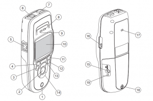
Physical Features
| Button No | Feature |
| 1) | On/off key. |
| 2) | Makes a selection on the screen. |
| 3) | Shows the previous screen. |
| 4) | Softkeys. The function of the softkey is shown above the key. |
| 5) | Cable test wire mapping input. Connect the cable from the top Ethernet port to this port to view the wire map details.
|
| 6) | Ethernet 10/100/1000BASE-X port. |
| 7) | Fiber port. Use one of the many supported SFP adapters to connect to the network. |
| 8) | Tx/Rx – The LED blinks when the tester transmits and receives data. |
| 9) | The LED is on when the tester is linked to the network. |
| 10) | Full-color LCD. |
| 11) | Softkeys. The function of the softkey is shown above the key. |
| 12) | Shows the Home screen. |
| 13) | Clears the current measurement data.
Saves the current measurements data into a report file which can be transferred to the LinkRunner Manager PC application and viewed/printed.
|
| 14) | Navigation keys. The outer ring of keys (four) perform the left/right and up/down screen navigation. |
| 15) | Connector for the ac adapter. |
| 16) | USB port for connection to a PC. |
| 17) | Kensington lock slot. |
| 18) | Screw for the battery pack. |
| 19) | The LED turns on when you connect the ac adapter. The LED is red when the battery is charging and green when the battery is fully charged.
|
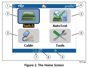
The Home Screen
| Button No | Feature |
| 1) | Shows the battery status. When the battery charge is low, the icon blinks. Connect the ac adapter to charge the battery and to make sure the tester continues to operate.
Shows that the ac adapter is connected.
Shows that the USB interface is connected. |
| 2) | Switch: Shows the advertised and actual link, PoE measurements, nearest switch with its name, type, IP address, port, slot, and VLAN information. |
| 3) | Cable: When the cable is connected un-terminated or is connected to a WireViewTM Office Locator, it shows cable information or wire mapping information. This can also be used to locate a cable with the optional IntelliToneTM probe. |
| 4) | The name of the tester profile. A profile contains the tester configuration settings. The default name is “Untitled”. The name shows an asterisk to the right of the name if you have changed a setting on the tester since you loaded or saved the profile. |
| 5) | AutoTest: Use Autotest to Ping and connect to selected targets. Up to 10 targets can be entered as a URL or IPv4/ IPv6 address along with the optional port number. When no port is specified, a Ping is performed. When the port is specified, a TCP SYN/ACK is performed. This is also referred to as a TCP Connectivity test. |
| 6) | Tools lets you manage files and settings. |
| 7) | Link established indicator. |
| 8) | Displays the link speed and duplex mode |
| 9) | Displays the connection type: PoE , 802.1x , fiber For 802.1x, a green lock indicates authentication passed, yellow indicates it is not needed, and a red closed lock indicates it failed authentication. |
Battery Charging and Life
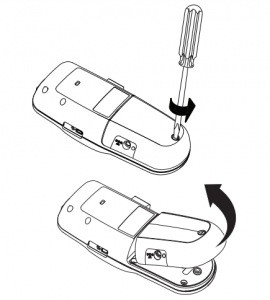
To charge the battery, connect the ac adapter to the battery connector (see Figure 1). You can use the tester while you charge the battery.
Above Figure shows how to replace the battery.
When the tester is off, the battery charges in approximately 3 hours.
Note
The battery will not charge if the internal temperature of the tester is above 113ºF (45ºC).
The battery life is approximately 6 hours during typical operation. An icon in the upper-left corner of the screen shows the battery status.
Common Questions LR-AT Can Solve
First connect an RJ-45 or fiber cable (2000 model only) from the network hub or wall plate to the LinkRunner AT RJ-45 LAN or fiber port. Check the following list of questions and associated answers to see how LinkRunner AT can help you get the job done.
Common Questions
Question
Is this a good RJ45 Ethernet cable?
Answer
Use Cable testing and the built in wiremap for patch cables, or an external WireviewTM Office Locator.
Question
Am I receiving a good fiber signal?
Answer
Connect to your network via a SFP adapter and validate the signal strength and link in the Switch screen.
Question
Where does this RJ45 cable go?
Answer
Use the Cable test toner function, Switch > Flash Port function, or Switch discovery protocol.
Question
Is this cable hooked up to anything?
Answer
Select Switch to identify an open cable, an active link, an un-powered network device or telephone voltage.
Question
Does this RJ45 drop support PoE?
Answer
Use Tools to specify the desired PoE power class and use Switch or AutoTest to verify the power under load up to 25.5W (802.3at).
Question
What speed/duplex is this device configured for?
Answer
Use Switch to check the advertised and actual speed/duplex. Additionally, use Tools to tests for manual (non-Auto Negotiated) speed/duplex.
Question
Can I see traffic from this connection?
Answer
Observe the utilization LED blinking to see network traffic.
Question
Can I connect in a MAC access control environment?
Answer
Use Tools > VLAN/MAC to specify a user defined MAC address.
Question
Do I have network connectivity?
Answer
Select AutoTest to validate key network services (DHCP, DNS, Router).
Question
Can I get an IPv4 DHCP address?
Answer
Select AutoTest. Select DHCP (or enter a static IP address) in the Tools > IP Configuration menu.
Question
Can I get an IPv6 address?
Answer
Enable IPv6 in Tools > IP Configuration. Use AutoTest to observer the acquired IPv6 link-local and global address.
Question
Can I PING?
Answer
Select AutoTest. Configure an address to Ping under Tools > AutoTest Configuration.
Question
Can I verify application connectivity?
Answer
Select AutoTest. Configure an address and application port (e.g. port 80 for web/HTTP) under Tools > AutoTest Configuration.
Question
Can I use it for throughput testing?
Answer
Use the Reflector tool (setup under Tools – only available on LR-AT 2000 model).
Question
Can I connect to an 802.1X port?
Answer
Use the Tools > Connect Configuration screen to enable 802.1X. Also, use the LinkRunner Manager PC application (select Tools > General Information to enable 802.1X and set up security).
Saving a Report
You can save the current measurement data the tester has collected into a report that can be viewed and printed through the LinkRunner Manager PC application. This information includes:
- AutoTest results
- Switch results
- Cable test results
Note
The LR-AT 1000 model can save up to 10 reports. The LR-AT 2000 model can save up to 50 reports
To save the measurement data collected on the tester:
- Press (save disk icon). The tester shows a default filename at the bottom of the screen.
- To save the data with the filename shown, press F2 Save. The tester saves the data into a report file.
- To overwrite a report that is saved on the tester, highlight the report, press (select), press (F2) Save, then press (F2) OK.
- To change the filename, press (F1) Edit
Note
Report names can have a maximum of 12 characters. The extension LRS is appended when the file is saved to your PC through the LinkRunner Manager PC application.
- To delete characters in the filename, press (F1) Backspace
- To add characters to the filename, use ( up and down, right and left button) to highlight a character, then press (select)
- To move the cursor in the filename, highlight the filename, then press press (side vol button right and left)
- To save the report with the edited filename, press (F2) Save, then press (F2)
To view the report, open it in LinkRunner Manager. Refer to the LinkRunner Manager help for instructions.
Set Up the Tester
To change settings on the tester, select Tools from the home screen.
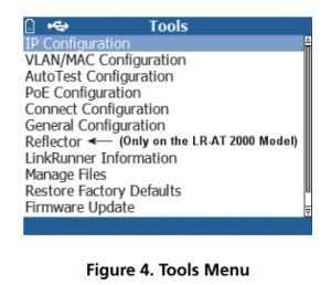
IP Configuration
Select Tools > IP Configuration
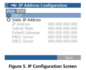
This screen allows you to enter an IPv4 address or use a DHCP address (default). It also allows you to enable IPv6 addressing (LR-AT 2000 only). LR-AT uses the IP address during AutoTest. During AutoTest, the LR-AT is required to connect to the network for Ping and TCP Connectivity testing.
At no other time, does the LR-AT connect to the network using IP addressing. This applies to the Switch and Cable test screens.
VLAN/MAC Configuration
Select Tools > VLAN/MAC Configuration.
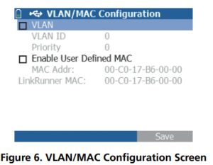
This screen allows you to enable and enter the VLAN IP and its Priority level. By un-checking the VLAN check box, the VLAN capability is disabled.
This screen also allows you to enable and enter a user defined MAC address. By un-checking the Enable User Defined MAC check box, the LR-AT reverts back to the factory default MAC address.
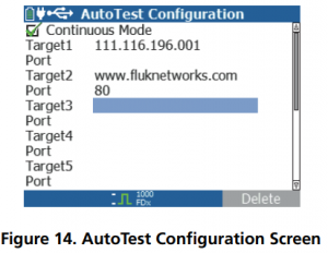
AutoTest Configuration
Select Tools > AutoTest Configuration
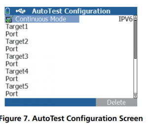
This screen allows you to enter up to ten key device addresses (Targets) to test connectivity. You may enter an IP address, URL, or DNS name. If no port is specified, AutoTest will perform an ICMP Ping test to that address. If a port is specified, AutoTest will perform a TCP Connectivity test (SYN/ACK).
The Continuous Mode check box allows the test to run continuously (checked) or one time (un-checked). When you exit the AutoTest screen, the test is stopped.
PoE Configuration
Select Tools > PoE Configuration.
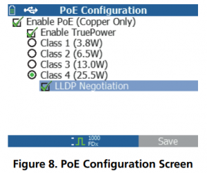
By default, PoE is disabled. This screen allows you to enable/ disable PoE detection, Enable TruePowerTM, and set the Class for detection. If you enable PoE and select Class 4 (25.5W), you can also enable LLDP Negotiation so that PoE is only reported if that criteria is met.
PoE TruePowerTM is only available on the LR-AT 2000 model. TruePowerTM puts a load on the PoE device and gives an accurate measurement on whether the device supports the Class selected.
Connect Configuration
Select Tools > Connect Configuration.
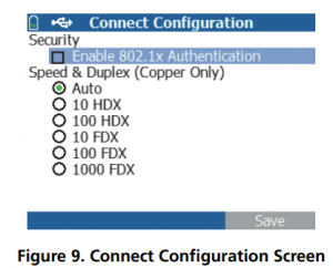
This screen allows you to enable 802.1x Authentication and set the speed/Duplex.
For 802.1x Authentication, if a certificate is required, you must transfer it from your PC using the LinkRunner Manager PC application provided with LR-AT. Only one certificate can be installed on a LR-AT at a time.
For Speed & Duplex, Auto is the default and recommended configuration. 10 HDX is 10 Mbps half duplex, 1000 FDX is 1000 Mbps full duplex.
General Configuration
Select Tools > General Configuration.
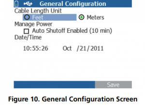
This screen allows you to set the units for the Cable test screen, Manage Power (10 minute automatic shutoff – default), and set the time/date.
Reflector Configuration (LR-AT 2000 Model)
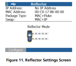
This screen is used to configure the LR-AT 2000 for remote access to Fluke Networks EtherScope Network Assistant, MetroScope Service Provider, and OptiView Analyzer’s throughput performance tests.
Note : The LR-AT 2000 can reflect jumbo frame sizes up to 9600 bytes.
Select Tools > Reflector. The default or pre-configured Reflector settings are displayed below
Select Configure
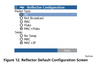
The LR-AT 2000 must to be configured to:
MAC + Fluke – This filter setting allows the LR-AT 2000 to only reflect packets when the destination MAC address field matches the LR-AT 2000’s own MAC address and Fluke payload.
MAC + IP – This swap setting allows the LR-AT 2000 to swap the source and destination MAC and IP addresses for packets that are reflected back to the analyzer.
Note: Any other Reflector setting may cause undesired traffic on your network.
LinkRunner Information
Select Tools > LinkRunner Information
This screen displays the following LR-AT product information:
Serial Number: The serial number is also shown under
the battery pack.
MAC Address: Media Access Control address. The unique address of the tester.
SW Version: The version of software in the tester.
Build: The build number of the software version.
Note: An SFP SX fiber adapter was connected to the tester in figure 13.
Manage Files
Manage Files allows you to load a profile, save a profile, save a report, rename a profile or report, or delete a profile or a report.
You can save reports on the tester and transfer them to the LinkRunner Manager PC application. Reports transferred to LinkRunner Manager can be displayed and printed. Reports contain the AutoTest, Switch, and Cable test results.
Profiles contain the following tester information: IP, VLAN/ MAC, AutoTest, PoE, Connect, General, and Reflector configurations. These settings can be modified in LinkRunner Manager and on the tester.
To Load a Profile
- Select Tools > Manage files.
- Select Load Profile.
- Select a Profile from the list.
To Save a Profile
- Select Tools > Manage files.
- Select Save Profile. The current setting are now saved to the profile filename shown at the bottom of the screen. To change the filename, select F1 Edit.
- Select F2 Save.
To Save a Report
- Select Tools > Manage files.
- Select Save Report. The current measurement data is now saved to the report filename shown at the bottom of the screen. To change the filename, select F1
- Select F2 Save or click on floppy disk icon on the top
To rename a file
- Select Tools > Manage files.
- Select Rename file.
- Highlight either the Report or Profile folder.
- Highlight the file, then press Select.
- To edit the filename, press F1
- To delete characters in the filename, press F1 Delete.
- To add characters to the filename, use arrow keys to highlight a character, then press left and right arrow keys.
- To move the cursor in the filename, highlight the filename, then press right and left keys
- To rename the file with the name you made, press F2 Save, then press F2 Rename.
To delete a file
- Select Tools > Manage files.
- Select Delete file.
- Highlight either the Report or Profile folder.
- Highlight a file, then press Select.
- Press F3
Restore Factory Defaults
Restores any configuration changes to the following LinkRunner AT factory defaults.
- IP Configuration:
IPv4: DHCP
IPv6: Disabled
- VLAN/MAC Configuration:
VLAN: Disabled
VLAN ID: 0
Priority: 0
User Defined MAC: Disabled
MAC Address: Linkrunner MAC address
- AutoTest Configuration:
Continuous Mode: On
Target: none
- PoE Configuration:
Enable PoE: Disabled
Class: Class 1
- Connect Configuration:
802.1x: Disabled
Speed/Duplex: Auto
- General Configuration:
Cable Length Unit, Meters
Auto Shutoff, Enabled
- Set Language:
English
When you Select Restore Factory Defaults, you will be prompted with a two popup. Select F2 OK, then press Select.
The restore will be completed and the tester will turn off
Firmware Update
- Download the LinkRunner firmware update file from the Fluke Networks website, or contact Fluke Networks to get the update by other means. Save the file to your hard disk.
- Get the latest version of LinkRunner Manager from the Fluke Networks website.
- Start LinkRunner Manager on your PC.
- Turn on the tester.
- Select Tools > Firmware Update > select A
- Use the USB cable supplied with the tester to connect the tester to the PC.
- In LinkRunner Manager, select LinkRunner > Update Software.
- Click Select, find and select the update file (.zip extension), then click Select.
- Click Update.
- When the transfer is completed, disconnect the USB cable from the tester.
- The screen on the tester goes blank while it installs the update file. When the update is completed, restart the tester.
Caution
Do not disconnect the LinkRunner from the PC or remove the battery during the update.
Transfer Saved Profiles to/from LinkRunner Manager
Use LinkRunner Manager to view and configure the profiles that are saved on the tester. To transfer profiles from the tester to LinkRunner Manager:
- Install the latest version of LinkRunner Manager software on your PC. Start the software.
- Turn on the tester.
- Use the USB cable supplied with the tester to connect the tester to the PC.
- To see the profiles that are on the tester, select Tools > Profile Manager from the LinkRunner Manager tool bar. Profile names display under the LinkRunner Profile Files pane.
- Highlight a profile in this pane and select Transfer from LinkRunner.
- When you are done editing the profile, highlight it and select Transfer to LinkRunner.
Set Language
To change the language displayed in all screens
- Select Tools > Set Language.
- Highlight a language and press B
Using AutoTest, Switch, and Cable Test
Using AutoTest
AutoTest can test up to ten targets. These targets can be local or off-net targets (devices). You can enter the IP address or a DNS name. If you specify a target address without specifying a port number, AutoTest will perform an ICMP Ping to the target address. If you specify a port number, AutoTest will perform a TCP Connectivity test (SYN/ ACK). See figures 14 and 15.
Select Tools > AutoTest Configuration and enter the target address(s). Entering a port number is optional.
AutoTest will attempt to Ping/Connect to the target device three times. If Continuous is selected, the test will run until you exit the AutoTest screen.
Select AutoTest on the Home screen. AutoTest will run and the test results should look similar to figure 15.
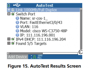
The nearest switch is discovered and its name, port, VLAN ID, model, and IP address are displayed. Then the DHCP server information is displayed. Finally, the Gateway and DNS server(s) are displayed along with the target device(s).
Expand on each device to display the test results as shown below.
Using the Nearest Switch Test
The Switch test screen displays the nearest switch. The nearest switch is discovered by locating the “port advertisement” on the first few packets seen by LR-AT.
Select Flash Port to stimulate the switch to flash the LED on the port that the LR-AT is connected into. This can help locate the switch port in the closet. Set the Flash Port flash rate from slow to fast to differentiate from the other switch port LED flash rates.
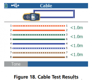
Using the Cable Test
There are three use models for using the Cable screen:
- Connect a cable from the top LR-AT RJ-45 connector into the side cable test RJ-45 connector to measure length and wire mapping.
- Connect an open cable (non-terminated) into the top LR-AT RJ-45 connector and measure length. An unterminated cable can also be traced using a Fluke Networks IntelliTone tester and the Tone function.
- Connect a cable into the top LR-AT RJ-45 connector and select Tone. Using a Fluke Networks IntelliTone tester, you can trace the wire or locate it in the switch closet.
Using PoE Feature
PoE is disabled by default. To enable PoE, select Tools > PoE Configuration, and check Enable PoE. Select the Class you want to verify. If you have purchased the LR-AT 2000, you can TruePowerTM test the Class. The results are displayed in the Autotest and Switch tests.
When you select a PoE Class higher than the switch can handle, LR-AT 2000 will provide the loaded results indicating the switch can not handle this Class setting. The LR-AT 1000 will display the unloaded results indicating voltage and wattage selected.
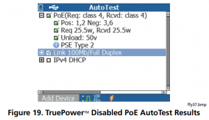
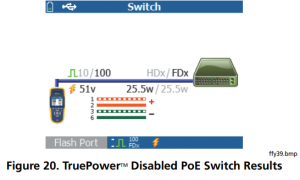
The following example was tested on a Class 3 (13w) switch. The tester PoE configuration was set to Class 4 (25w) with TruePowerTM disabled.
Figure 19 displays the AutoTest results and Figure 20 displays the Switch results. Notice in the Autotest results, the wire pair polarity, wattage requested and wattage received, voltage and PSE type are given.
PSE is the Power Sourcing Equipment rating, Type 1 (12.95W – 15.40W) and Type 2 (25.5W – 34.20W).
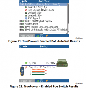
In the next example, the Switch results are shown with the same setup, i.e., no load, Class 4 (25.5w).
Using the Reflector Feature (LR-AT 2000 only)
The Reflector feature allows the LR-AT 2000 to be used as a remote device for Fluke Networks EtherScope Network Assistant, MetroScope Service Provider, and the OptiView Analyzer’s throughput performance tests.
See Reflector Configuration on page 14 for setting up this feature. Once set up, the device can be used as the remote responding device for throughput performance testing. There is no start or stop, and no results are displayed on the tester.
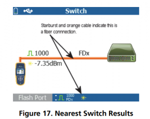
Using the Fiber Connection
Simply plug in the desired SFP adapter into the fiber port on the top of the tester and connect the fiber cable to the network. If both fiber and RJ-45 copper are connected to the network, the copper connection has priority.
Figure 23 shows the Switch results through a fiber connection with link, 1000 Mbps speed, full duplex, with a signal strength of 7.35dBm.

Maintenance
Warning
To prevent possible fire, electrical shock, personal injury, or damage to the tester:
- Do not open the case. You cannot repair or replace parts in the case.
- Use only replacement parts that are approved by Fluke Networks.
- If you replace parts that are not specified as replacement parts, the warranty will not apply to the product and you can make the product dangerous to use.
- Use only service centers that are approved by Fluke Networks.
Options and Accessories
Table shows options and accessories available for the LinkRunner AT Tester. For a complete list of options and accessories visit the Fluke Networks website
| Option or Accessory | Fluke Networks Model Number |
| Lithium ion battery pack for the LinkRunner tester | WBP-LION |
| Adapter/charger for connection to an automobile cigarette lighter | MS-Auto-Chg |
| AC adapter/charger, universal, 120-240 Vac | DTX-ACUN |
Specifications
| Operating temperature | 32ºF to 113ºF (0ºC to +45ºC) Note The battery will not charge if the internal temperature of the tester is above 113ºF (45ºC). |
| Operating relative humidity (% RH without condensation) | 90% (50ºF to 95ºF; 10ºC to 35ºC) 75% (95ºF to 113ºF; 35ºC to 45ºC) |
| Storage temperature | -4ºF to 140ºF (-20ºC to +60ºC) |
| Shock and vibration | Random, 2 g, 5 Hz-500 Hz (Class 2) 1 m drop |
| Safety | EN 61010-1 2nd edition EN/IEC 60825-1:2007, EN/IEC 60825-2:2004+ A1:2007 (LRAT-2000 only) |
| Altitude | 4,000 m; Storage: 12,000 m |
| EMC | FCC Part 15 Class A, EN 61326-1 |
| Certifications and compliance | Conforms to relevant European Union directives Conforms to relevant Australian standards Listed by the Canadian Standards Association |
General Specifications
| Media Access | 10BASE-T, 100BASE-TX, 1000BASE-T (IEEE-802.3) and Poe (IEEE 802.3at) |
| Cable Test | Pair lengths, opens, shorts, splits, crossed, straight through, and cable ID |
| Tone Generator | IntelliTone digital tone: [500 KHz]; analog tones: [400Hz, 1KHz] |
| Ports | RJ45 copper port 1000BASE-X fiber adapter port (2000 only) |
| Dimensions | 3.5 in x 7.8 in x 1.9 in (8.9 cm x 19.8 cm x 4.8 cm) |
| Weight | 18 oz (0.5 kg) |
| Battery | Removable, rechargeable lithium-ion battery pack (18.5 Watt-hrs) |
| Battery life | Typical operating life is 6 hours. Typical charge time is 3 hours. |
| External AC adapter/charger | AC input 90-264 Vac 48-62 Hz input power DC output 15 Vdc at 1.2 amps |
| Display | 2.8 in color LCD (320 x 240 pixels) |
| Keypad | 12-key elastomeric |
| LEDs | 2 LEDs (transmit and link Indicators) |
| Host interface | USB 5-pin mini-B |
LinkRunner Manager Software
| Supporting operating system | Windows Vista, Windows XP, Windows 7 |
| Processor | 400 MHz Pentium processor or equivalent (minimum); 1 GHz Pentium processor or equivalent (recommended) |
| RAM | 96 MB (minimum); 256 MB (recommended) |
| Hard disk | Up to 500 MB of available space may be required |
| Display | 1024 x 768 high color, 32-bit (recommended) |
| Hardware | USB Port |